|
иҜҰз»ҶиҜҙжҳҺ ж ҮеҮҶдҝЎеҸ·йҡ”зҰ»ж”ҫеӨ§еҷЁ VariTrans® P 15000 knick
The professional standard signal amplifier; with calibrated range selection and broad-range power supply

|
 |
|
Product description
|
|
|
Image Typical applications
|
|
|
Facts
|
|
|
Product Line
|
|
|
|
Dimension drawings
|
|
|
Schematic diagram
|
|
|
Specifications
|
|
|
Downloads
|
|
|
|
|
|
|
The Task
Industrial applications require the transmission and conversion of different standard signals (0 ... 20 mA, 4 ... 20 mA and 0... 10 V) with high accuracy.
The Problems
Long transmission paths can cause potential differences that lead to errors in the measuring result. Furthermore different products would be required for different signals and supply voltages.
The Solution
The VariTrans® P 15000 isolation amplifier from Knick features excellent transmission quality combined with the calibrated standard signal switching using DIP switches and a broad-range power supply.
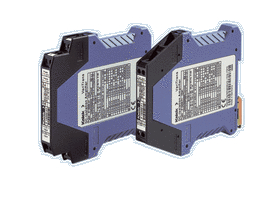
The Housing
At just 12.5 mm wide, the modular housing with pluggable screw terminals allows simple and fast assembly and prewiring of enclosures. Housings with fixed screw terminals are also available for extremely high mechanical loads.
The easy-to-open housing allows easy configuration of the input and output ranges and good protection against touch and unintended adjustment.
The Advantages
The analog transmission of the measuring signal with transformer isolation and the new digitally controlled measuring range selection guarantee almost perfect signal transmission:
• Gain error only 0.08 %
• Excellent pulse formation
• Extremely low residual ripple
• Maximum long-term stability and reliability
The Technology
A microcontroller monitors the control element settings and controls the calibrated range selection. Interference to the signal transmission – for example, due to contact resistances in the range switches – is thus ruled out.
Thanks to the VariPower® power supply, the devices can be used all over the world for all common supply voltages from 20 to 253 V AC/DC with almost any power supply. The extremely low power consumption and the related minimal self-heating significantly increase the reliability. That’s why we give a 5-year warranty.
| Facts |
| |
- Flexible and highly accurate: calibrated range selection without complicated recalibration
- VariPower® 20 ... 253 V AC/DC broad-range power supply
- Extremely compact design: 12.5mm modular housing, up to 80 active isolators per meter of top-hat rail
- Fast and easy configuration: housing simple to open
- Pluggable screw terminals: simple, time-saving assembly and prewiring of enclosures
- 3-port isolation: protection against incorrect measurements or damage
- Maximum accuracy
- Individual test report following EN 10204 2.3
- Protective separation according to EN 61140, protection against unpermitted high voltages
- Maximum reliability: no repair and failure costs
- 5-year warranty
|
| Product line |
| |
| Devices |
|
|
Order no. |
Order no. |
|
|
|
| |
|
|
With pluggable |
With fixed |
| |
Input |
Output |
screw terminal |
screw terminal |
|
|
|
| VariTrans® P 15000 with calibrated |
0 ... 20 mA, |
0 ... 20 mA, |
P 15000 H1 |
P 15000 F1 |
| input and output selection |
4 ... 20 mA, |
4 ... 20 mA, |
| |
0 ... 10 V |
0 ... 10 V |
|
|
|
| VariTrans® P 15000 with |
0 ... 20 mA |
0 ... 20 mA |
P 15016 H1 |
P 15016 F1 |
| fixed settings |
0 ... 20 mA |
4 ... 20 mA |
P 15017 H1 |
P 15017 F1 |
| |
0 ... 20 mA |
0 ... 10 V |
P 15018 H1 |
P 15018 F1 |
| |
4 ... 20 mA |
0 ... 20 mA |
P 15026 H1 |
P 15026 F1 |
| |
4 ... 20 mA |
4 ... 20 mA |
P 15016 H1 |
P 15016 F1 |
| |
4 ... 20 mA |
0 ... 10 V |
P 15028 H1 |
P 15028 F1 |
| |
0 ... 10 V |
0 ... 20 mA |
P 15036 H1 |
P 15036 F1 |
| |
0 ... 10 V |
4 ... 20 mA |
P 15037 H1 |
P 15037 F1 |
| |
0 ... 10 V |
0 ... 10 V |
P 15038 H1 |
P 15038 F1 |
| |
| "Specific Test Report" included in delivery. |
| |
| Power supply |
|
|
| 20 ... 253 V AC/DC |
| |
| Accessories |
|
|
| Test certificate according to KTA 3507 |
|
|
|
ZU 0659 |
| |
| |
Dimension drawings and terminal assignments
|
|
|

|
|
|

|
|
| Specifications |
| |
| Input data |
|
|
|
| Inputs |
0 ... 20 mA |
Terminal-selectable/switchable (factory setting 0 ... 20 mA) |
| |
4 ... 20 mA |
or fixed settings (see Product line) |
| |
0 ... 10 V |
|
|
|
| Input resistance |
Current input |
Voltage drop approx. 250 mV at 20 mA |
| |
Voltage input |
Approx. 1 Mohm |
|
|
|
| Overload |
Current input |
≤300 mA |
| |
Voltage input |
Voltage limitation with suppressor diode 30 V, |
| |
|
max. permitted continuous current 30 mA |
| |
| |
| Output data |
|
|
|
| Outputs |
0 ... 20 mA |
Switchable (factory setting 0 ... 20 mA |
| |
4 ... 20 mA |
or fixed settings (see Product line) |
| |
0 ... 10 V |
| |
(transmission of negative measuring signals up to approx. –5 % of full scale) |
|
|
|
| Load |
With output current |
≤12 V (600 ohms at 20 mA) |
| |
With output voltage |
≤10 mA (1 kohm at 10 V)1) |
|
|
|
| Offset |
20 µA or 10 mV |
|
|
|
| Residual ripple |
<10 mVrms |
| |
| |
| Transmission behavior |
|
|
|
| Gain error |
<0.08 % meas. val. (DC) |
|
|
|
| Cut-off frequency |
>10 kHz – 3 dB, P 15000 F1/H1 switchable to <10 Hz –3 dB |
|
|
|
| Temperature coefficient 2) |
0.005 %/K full scale (reference temperature 23 ºC) |
| |
| |
| Power supply |
|
|
|
| Power supply |
20 ... 253 V AC / DC |
AC 48 ... 62 Hz, approx. 2 VA |
| |
|
DC approx. 0.9 W |
| |
| |
| Isolation |
|
|
|
| Galvanic isolation |
3-port isolation between input, output and power supply |
|
|
|
| Test voltage |
4 kV AC input against output against power supply |
|
|
|
| Working voltage |
1000 V AC/DC with overvoltage category II and pollution degree 2 according to EN 61010-1 |
| (basic insulation) |
For applications with high working voltages, you should ensure there is sufficient spacing or isolation from neighboring devices and protection against electric shocks. |
|
|
|
| Protection against |
Protective separation according to EN 61140 by reinforced insulation in accordance with EN 61010-1. |
| electric shock |
Working voltages up to 300 V AC/DC across input and output and power supply with overvoltage category II and pollution degree 2. |
| |
For applications with high working voltages, you should ensure there is sufficient spacing or isolation from neighboring devices and protection against electric shocks. |
| |
| |
| Standards and approvals |
|
|
|
| Surge withstand |
5 kV 1.2 / 50 µs according to IEC 255-4 |
|
|
|
| EMC 3) |
EN 61326 |
|
|
|
| Approvals |
cUL: |
File no. E 216767, Standards UL 3101-1, CSA-C 22.2-95, No. 10101-1 |
| |
GL: |
No. 14593-99 HH |
| |
KTA: |
3507 |
| |
| |
| Other data |
|
|
|
| MTBF4) |
Approx. 91 years |
|
|
|
| Ambient temperature |
Operation: |
–10 ... +70 ºC |
| |
Transport and storage: |
–40 ... +85 ºC |
|
|
|
| Housing |
Modular housing, width 12.5 mm, see dimension drawing for other measurements |
| |
Pluggable screw terminals: |
Type H1 |
| |
Fixed screw terminals: |
Type F1 |
|
|
|
| Protection class |
IP 20 |
|
|
|
| Mounting |
Metal lock for mounting on 35-mm top-hat rail according to EN 50022 |
| |
See dimension drawings for conductor cross section |
|
|
|
| Weight |
Approx. 150 g |
| |
| |
| |
| 1) Higher voltage output load on request |
| 2) Average TC in specific working temperature range –10 ºC ... +70 ºC |
| 3) Slight deviations are possible during interference |
| 4) Mean Time Between Failures - MTBF - to EN 61709 (SN 29500). Conditions: stationary operation in well-tended rooms, average ambient temperature 40 °C, no ventilation, continuous operation |
| |
|